Keyboard
Ex-MoD Keyboard project
This project has been on the backburner a while.. I originally picked up this AT-02 Marconi / MEDL keyboard a few years ago (2017), did not originally get to far, then jumped back on the project in early 2020. As far as I can see it’s a British military keyboard from 1989, but after a lot of research I could not confirm where it was originally used. It has a few interesting buttons such as: XALM, EW (electronic warfare?), MSGQ GET, PRNT SUSP, WPNS HOLD. If anyone has any insights as to what this would have been used for, I’d love to know.
Some model specs of the keyboard:
AT02 / AT-02 Marconi / Marconi Electronic Devices Ltd (MEDL)
NSN 7025-99-588-1302 (first seen 1989)
2162-03025-02-3-T
After a couple of aquisitions in the 90s, 2000s, MEDL now exists under Dynex Semiconductor Ltd.

Opening up the keyboard
First step is to checkout the keyboard PCB/Matrix itself. The connector on the inside of the keyboard is a MIL-STD 26pin proprietary connector. This connects to a ribbon cable directly on the board.
The downside of this board is that the control circuit is embedded in a multi-layer PCB along with the keyboard matrix. Normally keyboards will have the matrix as a separate board, with the control circuit separate to the matrix itself. If the custom control circuit was separate from the matrix, this would have been much easier to work with.
The keyboard matrix, PCB top side, with the rubber buttons used to close the circuits
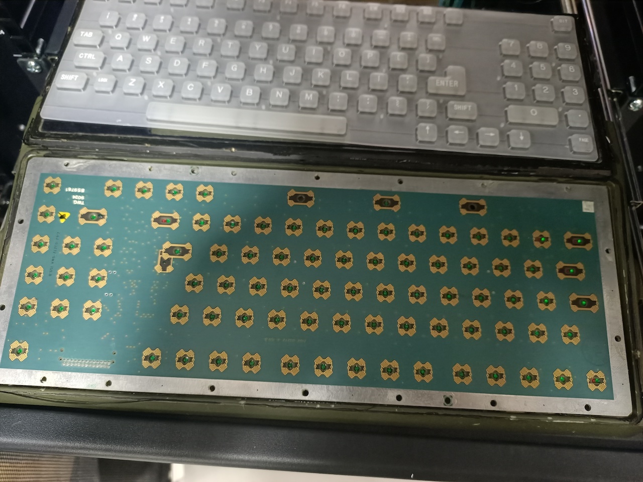
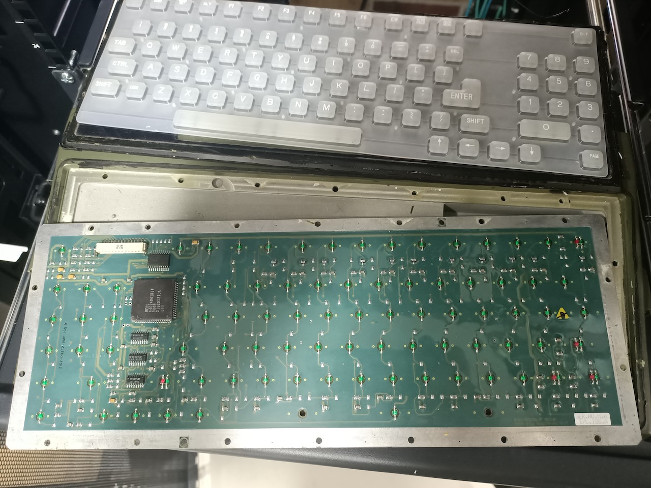
The bottom of the PCB, showing the custom controller circuit, ribbon cable connector, and SMD LEDs for the backlights
After tracing the pins from the ribbon cable connector, I found that none of the pins represent any of keyboard matrix columns or rows.
How keyboard matrixes work, and decoding them
Keyboards typically use rows and columns connnected by the keyboard switches. Scanning each row and column allows the control circuit to determine which key is pressed, without needing an input per switch.
This particular keyboard was 8 rows with 11 columns, giving a max of 88 keys.
Tracing a keyboard matrix: This is a relatively simple process, but time consuming. In an ideal world, each row and column of a keyboard would roughly line up with the actual keyboard layout, but this is almost never the case.
To trace a keyboard you need to systematically trace which switches are connected to each other. Starting with the terminnal from one side of the switch, with an Ohmmeter find out which keys are connected to it. Repeat this for each key, you’ll eventually see a pattern of rows or columns. The columns will all be terminated to one side of a switch, the rows to the other side.
Once you’ve done this, you can number each column and row, then the next step is to work out where on the PCB these terminate.. after confirming the ribbon cable pinout didn’t connect directly to the matrix, I checked out the custom MEDL chip. As somewhat expected, 19 of the PLCC pins connected directly to each of the 8x11 keyboard matrix outputs.
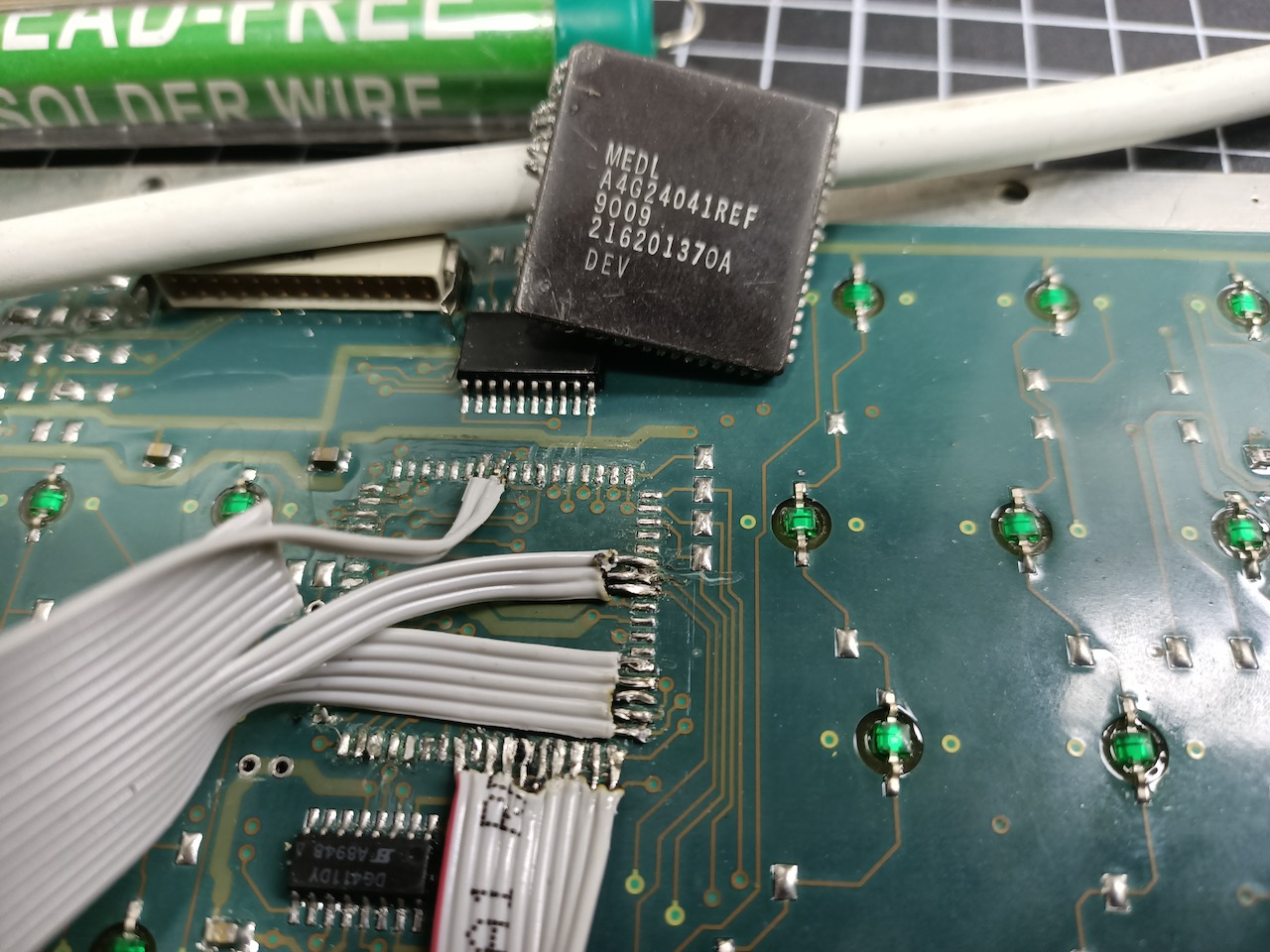
The complicated step here is connecting a ribbon cable to where the PLCC 68 chip is situated, if this was a more normal keyboard, the terminals may already have terminals elsewhere that would be more accessible by a control circuit. However, this required removing the chip, and directly soldering the ribbon cable to the pins we care about.
Removing the custom PLCC 68, replacing the relevant row/column pins with a ribbon cable.
Connecting to a new USB HID controller
Once you have access to the matrix, you have a number of options. Firstly, you need a board which allows for a USB HID interface, so you can natively use it as a Keyboard (or mouse) input.
Here’s a couple of options:
- Teensy (many models)
- Arduino Leonardo
I opted for a Leonardo, only because the local store had them in stock, I otherwise would have opted for a Teensy. Just ensure you have enough digital I/O pins for the rows and columns in your circuit. I had 19 (8x11), the Leonardo has 20x digital pins, so this was fine.
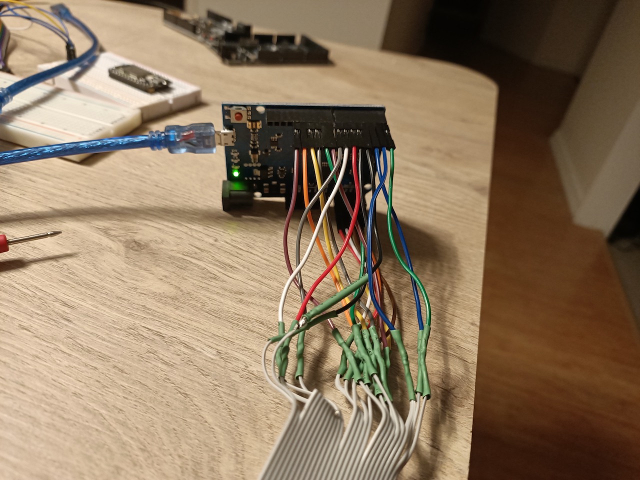
The next step is connecting all the pins to your chosen board, I chose pins 0-7 for the rows, and 8-13 and A0-A4 for the columns. A0-A4 are analog pins on the Leonardo, but can be used as digital I/Os.
Connecting all the ribbon cable pins to a Leonardo
From here, the code options are equally unlimited, there’s default libraries around for interacting with keypads/keyboard matrixes. I opted for the Keypad arduino library. Depending on the library, and the setup of your matrix (whether diodes are used etc), you may be susceptible to ghosting or shorting if trying to detect multiple keypresses at once. If you use the above Keypad library, you should be fine for one press at a time.
There’s various code examples for the libraries, but the they mostly include defining the pins used for the rows and columns as well as a keymap.
Arduino Keyboard HID library
Arduino has a default Keyboard library that replicates a standard keyboard.
Installation: If you’ve not used this before, goto Manage Libraries, then search for Keyboard, then install Keyboard Built-in by Arduino.
Small example on using the library, checkout the Keyboard Modifiers Reference:
#include <Keyboard.h>

Keyboard.write("Hello");
Keyboard.write('c');
Keyboard.write(KEY_LEFT_CTRL);
Setup of the keyboard/keypad
The below is the definition of the keypad object, with the relevant number of rows and columns. The keys object contains the keymap, with upper_keys being the upper case keys. If you’ve planned ahead in mapping your key matrix to the relevant keys, you should already know what these values are, if not, you can manually go through each row, test the keys, and update the key mapping.
I used hex for the special keys here, only because I started working on the code being pulling in the keyboard library which includes the key definitions.
const byte ROWS = 8;
const byte COLS = 11;

char keys[ROWS][COLS] = {
  {NO_KEY,NO_KEY,NO_KEY,NO_KEY,0xD3,0xD9,0x85,0xD7,0xD8,0xDA,0x20},
  {'0','.','3','2','5','4','6','9','8','7','1'},
  {'<','/',0xB0,'\'',0xB2,'=','[',0xCB,0xCA,0xC9,']'},
  {';',':','m','n','c','x','v','z',0xC1,0x81,'b'},
  {'o',NO_KEY,'k','j','f','e','g','s','a',0x80,'h'},
  {0xC7,0xC8,0xC6,0xC5,0xC2,0x82,0xC3,0xD2,0x83,0xB1,0xC4},
 {'l','p','i','u','r','d','t','w','q',0xB3,'y'},
  {'0','-','9','8','5','4','6','3','2','1','7'},

};

char upper_keys[ROWS][COLS] = {
  {NO_KEY,NO_KEY,NO_KEY,NO_KEY,0xD3,0xD9,0x85,0xD7,0xD8,0xDA,0x20},
  {')','.','#','@','%','$','^','(','*','&','!'},
  {'>','?',0xD3,'"',0xB2,'+','{',0xCB,0xCA,0xC9,'}'},
  {';',':','M','N','C','X','V','Z',0xC1,0x81,'B'},
  {'O',NO_KEY,'K','J','F','E','G','S','A',0x80,'H'},
  {0xC7,0xC8,0xC6,0xC5,0xC2,0x82,0xC3,0xD2,0x83,0xB1,0xC4},
 {'L','P','I','U','R','D','T','W','Q',0xB3,'Y'},
  {')','_','(','*','%','$','^','#','@','!','&'},

};


byte rowPins[ROWS] = {0,1,2,3,4,5,6,7}; //connect to the row pinouts of the keypad
byte colPins[COLS] = {8,9,10,11,12,13, A0,A1,A2,A3,A4}; //connect to the column pinouts of the keypad

Keypad keypad = Keypad( makeKeymap(keys), rowPins, colPins, ROWS, COLS );
Now we have the keypad defined, we need to be able to actually read the key presses and push to the keyboard object.
The most simple implementation would look something like the below, all we’re doing here is fetching the key, checking a key is pressed, then pushing to the keyboard.
void loop(){
  char key = keypad.getKey();

  if (key != NO_KEY){
  	Keyboard.print(key);
  }
}
The above covers very simple keypads and keyboards, but to deal with shift, and caps lock, we need a bit more work.
void loop(){
  char key = keypad.getKey();
  char upper;
  upper = findKey(key);
    //if we're in shift lock, shift mode, send the upper key, and reset shift state
    if ((shift_state == 1 || shift_state == 3) && !(keypad.isPressed(0x81) || keypad.isPressed(0x85) || keypad.isPressed(0xC1) ))
    {
      if (key != NO_KEY){
        Keyboard.write(upper);
      	if (shift_state == 1)
          shift_state = 0;
      }
    } else {

    if (key != NO_KEY){
      if (keypad.isPressed(0x81) || keypad.isPressed(0x85)){
        //if either shift key is set, set temporary shift lock
        shift_state = 1;
      }
      else if (keypad.isPressed(0xC1)) {
        //Caps lock pressed
        if (shift_state == 3) //clear if already set
          shift_state = 0;
        else
          shift_state = 3; //set shift lock
      } else {
        shift_state = 0;
        Keyboard.write(key);
      }

    }
   }
}
Backlight
Tracing the backlight circuit was relatively straightforward as it’s on the exposed side of the PCB, however, it seems it’s powered in columns.. possibly a brightness circuit, to avoid entirely working out the custom controller further, I just bridged the columns and powered them all together.
Success!